Anti-freeze protection


The unit is consisting of:
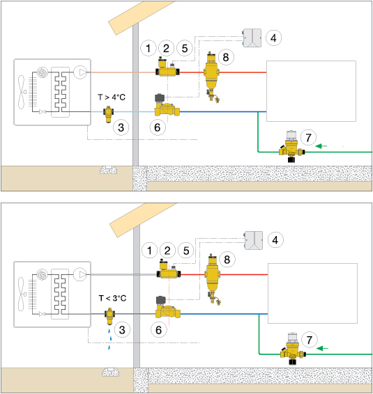
1. Automatic air vent.
2. Check valve, 1” male connections.
3. Anti-freeze valve, 1” male connections.
4. Control unit.
5. Minimum temperature thermostat.
6. NC solenoid valve, 230 V - 50 Hz.
Operating principle
The anti-freeze protection unit code 109610 can be installed when the heat pump has an internal circulator.
The system actuates in the event of failure of electric supply to the heating system or should the heat pump malfunction. In the event of a electric supply failure, the system separates the internal part of the system from the outside part at the level of the check valve (2) and the normally-closed solenoid valve (6). If the water temperature inside the pipes remains above 4°C, the anti-freeze valve obturator stays closed and the pipe remains in pressure. When the water temperature in the pipes reaches 4°C, the thermostat in the anti-freeze valve (3) allows the obturator to open and drain the water in the outside part of the pipes. When electric supply returns, the solenoid valve opens, the filling unit (7) recharges the system to the nominal pressure setting and the anti-freeze valve closes, allowing circulation in the system to restart: the air vent (1) and deaerator-dirt separator (8) remove any excess air. In the event of a heat pump failure, with subsequent drop in the water temperature within the system (the circulation pump keeps running but there is no longer any heat exchange in the machine), the safety thermostat (5) would operate. When the water reaches a temperature of 10°C, the thermostat (5) actuates and via the regulator (4) stops the electric supply to the solenoid valve, thereby triggering the procedure described above for electric supply failures.
Our range
Serie 109 ... Anti-freeze kit
Serie 108 ... Anti freeze valve
Sheme