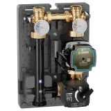
Motorised regulating unit DN 25, for heating and cooling systems.
Product Description
Motorised regulating unit DN 25, for heating and cooling systems.
Right - left convertible.
Available with three-point control signal actuator (note A) or 0(2)–10V control signal and 0–10V feedback signal (note B).
Regulation with sector three-way valve.
With insulation.
Technical data
Maximum working pressure:
10 bar
Medium temperature range:
5–100 °C
Outlet centre distance:
125 mm
Type of pump:
UPM3K Auto 25-70
Note
Note A: three-point control signal actuator.
Operating time: 150 s.
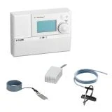
Can be combined with regulators code 161010 and 1520 series.
Note B: 0(2)–10 V control signal actuator.
Feedback signal: 0–10 V.
Operating time: 75 s.
Can be combined with regulator code 161010 (for actuator electic supply use 230V / 24V transformer).
Certifications

Download
Drawings and specifications
| Part number | System side connection | Boiler side connection | Note |
|---|---|---|---|
| 167652HE1 | G 1" (ISO 228-1) F |
G 1 1/2" A (ISO 228-1) M |
A |
|
Electric supply
230 V AC
|
Flow rate with available head 4 m w.g.
1,4 m3/h
|
||
|
2D drawings
3D models
Tender text
Motorised regulating unit DN 25, for heating and cooling systems.
With insulation.
Right - left convertible.
Available with three-point control signal actuator (note A) or 0(2)–10V control signal and 0–10V feedback signal (note B).
Regulation with sector three-way valve.
System side connection: G 1" (ISO 228-1) F. Boiler side connection: G 1 1/2" A (ISO 228-1) M. Maximum working pressure: 10 bar. Medium temperature range: 5–100 °C. Electric supply: 230 V AC. Outlet centre distance: 125 mm. Flow rate with available head 4 m w.g.: 1,4 m3/h. Type of pump: UPM3K Auto 25-70.
SCIP code
89b73ae3-da88-4a8e-92ac-196b6d0a472d
|
|||
| 167654HE1 | G 1" (ISO 228-1) F |
G 1 1/2" A (ISO 228-1) M |
B |
|
Electric supply
24 V AC
|
Flow rate with available head 4 m w.g.
1,4 m3/h
|
||
|
3D models
Tender text
Motorised regulating unit DN 25, for heating and cooling systems.
With insulation.
Right - left convertible.
Available with three-point control signal actuator (note A) or 0(2)–10V control signal and 0–10V feedback signal (note B).
Regulation with sector three-way valve.
System side connection: G 1" (ISO 228-1) F. Boiler side connection: G 1 1/2" A (ISO 228-1) M. Maximum working pressure: 10 bar. Medium temperature range: 5–100 °C. Electric supply: 24 V AC. Outlet centre distance: 125 mm. Flow rate with available head 4 m w.g.: 1,4 m3/h. Type of pump: UPM3K Auto 25-70.
SCIP code
f38b1e3c-417c-4e2c-8a03-4dc556b9ef7b
|
|||


