COMPONENTS FOR HEAT PUMP SYSTEMS

ANTIFREEZE VALVES

108

Operating principle

The antifreeze valve allows the medium in the system serving the heat pump to be drained from the circuit when its temperature reaches an average value of 3 °C.

This prevents ice from forming, thereby avoiding potential damage to the machine and pipes. 

The version with air sensor allows system operation in cooling mode, even when the temperature of the water is around 3 °C. In these conditions the air sensor cuts in to prevent water drainage.

The formation of ice in heat pump systems

108

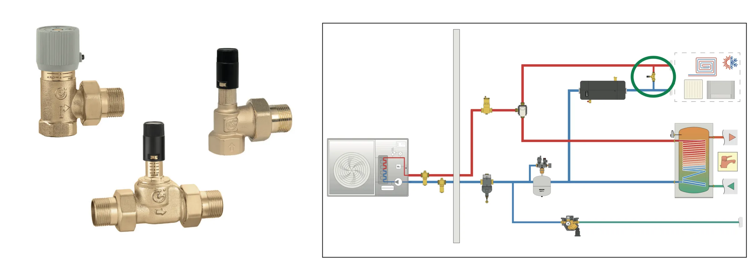
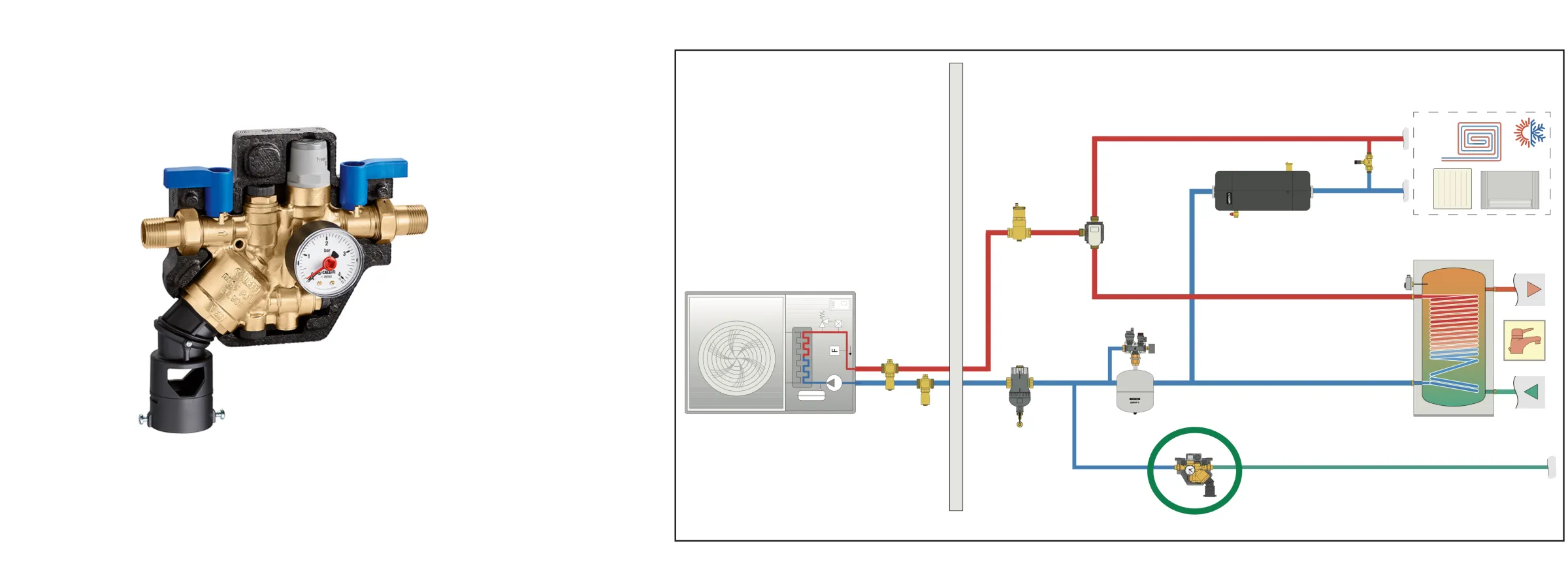
In monobloc and hydro-split systems, the hydraulic circuit has an external section which connects the heat pump to the rest of the system. This section, although short and well insulated, may be at risk of frost in certain sub- zero temperature conditions. 

In the event of simultaneous frost-blackout conditions, this may cause significant damage to the gas/water heat exchanger in the machine. 

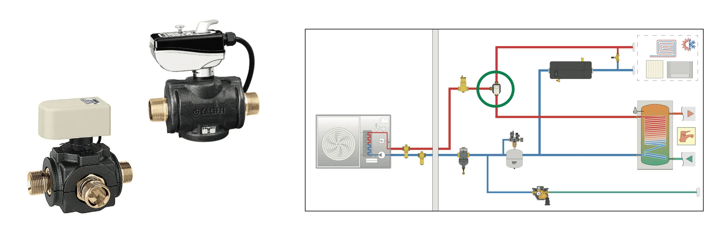
Manufacturers request that glycol is added to the water in the system, or that special antifreeze valves are used. Using glycol can be financially demanding and presents a series of disadvantages (see box opposite). An antifreeze valve is a mechanical protection system offering an alternative to the use of glycol.

MAGNETIC FILTERS

XF

Operating principle

The impurity separating action of the magnetic filter is based on the combined action of several components:

  • an internal mesh element (1), which carries out dirt separation;
  • magnets fitted directly in the flow path (2), which capture and retain ferrous impurities;
  • a metal filter mesh (3), which separates off the impurities by means of mechanical selection.
XF

The filter mesh is characterised by various parameters, one the most important being the mesh size (or filtering capacity), which indicates the minimum dimensions of the particles that the filter is able to intercept. 

Another concerns the filter mesh surface, with a larger surface area guaranteeing a lower degree of fouling. Due to its passage through the filter mesh, a pressure drop is produced in the medium which increases as the degree of clogging increases. 

In combined devices such as dirt separator filters, the filter mesh is better protected than that of a simple filter because some of the impurities fall into the dirt separator. This means there is less fouling than in normal filters within the same operating time.

Impurities in heat pump systems

XF

The components of a heating and cooling system are exposed to degradation caused by the impurities that circulate in the thermal medium. If the impurities are not removed as necessary, they may cause blockages and seizing of the pumps, lower efficiency of the heat exchangers, unreliable valve operation and insufficient heat exchange. 

In the specific case of a heat pump system, the impurities may put the already small inner channels at risk of blockage, or prevent the internal adjustment devices from working properly. As the heat pump is a generator employing low temperature differences, even small changes in flow rate may adversely affect its performance. 

The greater the filtering action of the magnetic dirt separator filter, the longer the high efficiency of the heat pump systems will be maintained.

DEAERATORS

551

Operating principle

Deaerators are used to continuously remove the air contained in the hydraulic circuits of heating and cooling systems. They are capable of automatically removing all the air present in the system down to micro-bubble level. 

The fully deaerated medium allows systems to operate under optimal conditions, free from any noise, corrosion, localised overheating or mechanical damage.

DEAERATORS - DIRT SEPARATORS

5464

Operating principle

Deaerators-dirt separators are used to continuously eliminate the air and dirt contained in the hydraulic circuits of heating and cooling systems. They are capable of automatically removing all the air from the system down to micro-bubble level. 

At the same time they separate dirt and impurities contained in the water within the circuit and collect them in the lower part of the valve body, from which they may be discharged. The magnet separates ferrous impurities. 

The circulation of fully deaerated medium enables the system to operate under optimum conditions, free from any noise, corrosion, localised overheating or mechanical damage.

BUFFER TANK-HYDRAULIC SEPARATOR FOR HEAT PUMPS

5485

Operating principle

In some operating modes the heat pump needs to dispose of the energy in the machine compressor utilising the circulation of the medium, or it has to perform a heat exchanger defrost cycle in specific outside ambient conditions. 

In these cases the machine needs an amount of thermal energy to always be available and a minimal water flow rate which would be less in the event that the zone valves in the secondary circuit are closed. An inertial storage installed in line within the system can be used to guarantee the required thermal energy. 

To ensure the minimum flow rate in this configuration, a by-pass valve must be fitted between the flow and return. The alternative is to have a built-in volume in the separator itself, which also guarantees the minimum flow rate required.

INSTRUMENT HOLDER AND EXPANSION VESSELS

305_556

DIVERTER VALVES

6445_638

Operating principle

Motorised diverter valves are used to manage the flow between the heating and cooling system and the domestic water system. Management is generally entrusted to the electronics of heat pump, via a probe installed on the domestic water boiler. 

Diverting the flow is completely effective when there is no leakage and when the operating time is short. For this very reason, three-way ball diverter valves are preferable to those with pistons due to their shape. 

The motorised valve must have an operating time no greater than 50 seconds, in order to optimise DHW production processes.

DIFFERENTIAL BY-PASS VALVES

519_518

Operating principle

In heat pump systems, the circulation of a minimum flow rate must always be guaranteed. If the system is divided into a primary and secondary circuit, this flow rate is guaranteed by the hydraulic separator. 

In other cases a by-pass valve (or differential by-pass valve) is typically used, fitted at the end of the line before any potential shut-off points (zone valves) controlled by the thermostats. 

The valve must be installed after the inertial storage so that it can always utilise the thermal energy required when the machine is working.

DISTRIBUTION MANIFOLD

110

Operating principle

110

The ground contains a large amount of heat from two origins: one external and one internal. Heat from external sources comes mainly from sun and rain and penetrates the outer layers of the earth up to a depth of 15 metres. 

Heat from inside is generated by the nuclear decay of radioactive substances in rocks and the substratum: this is the source that heats the soil to a depth of more than 20 metres which can be defined as geothermal heat. 

Geothermal heat pumps use this type of energy: the heat exchange between the ground and the system takes place via the closed circuit probes, which may be vertical or horizontal.

AUTOMATIC CHARGING UNIT WITH BACKFLOW PREVENTER

580

Operating principle

The charging unit and hydraulic backflow preventer assembly performs two combined actions which are required for the system to work:

  1. it keeps the system pressure at an optimal level (charging unit), usually 1.5 bar; 
  2. it prevents the water in the system from returning inside the domestic hot water circuit (hydraulic backflow prevention). 

Hydraulic backflow preventer usage is governed by reference standard EN 1717:2000 “Protection against pollution of potable water in water installations and general requirements of devices to prevent pollution by backflow”. This standard classifies the water in the systems into five categories according to the level of risk it represents for human health.

The water contained in the thermal system in most cases may fall into category 3 (“Medium presenting some hazard to human health due to the presence of one or more harmful substances”), or category 4 (“Medium presenting a hazard to human health due to the presence of one or more toxic or very toxic substances”). 

According to this classification, suitable backflow prevention devices must be fitted in water distribution circuits.

Find a store

Components for heat pump systems