iStop®, Anti-freeze valve for air-to-water hydronic heat pump applications


Product Description
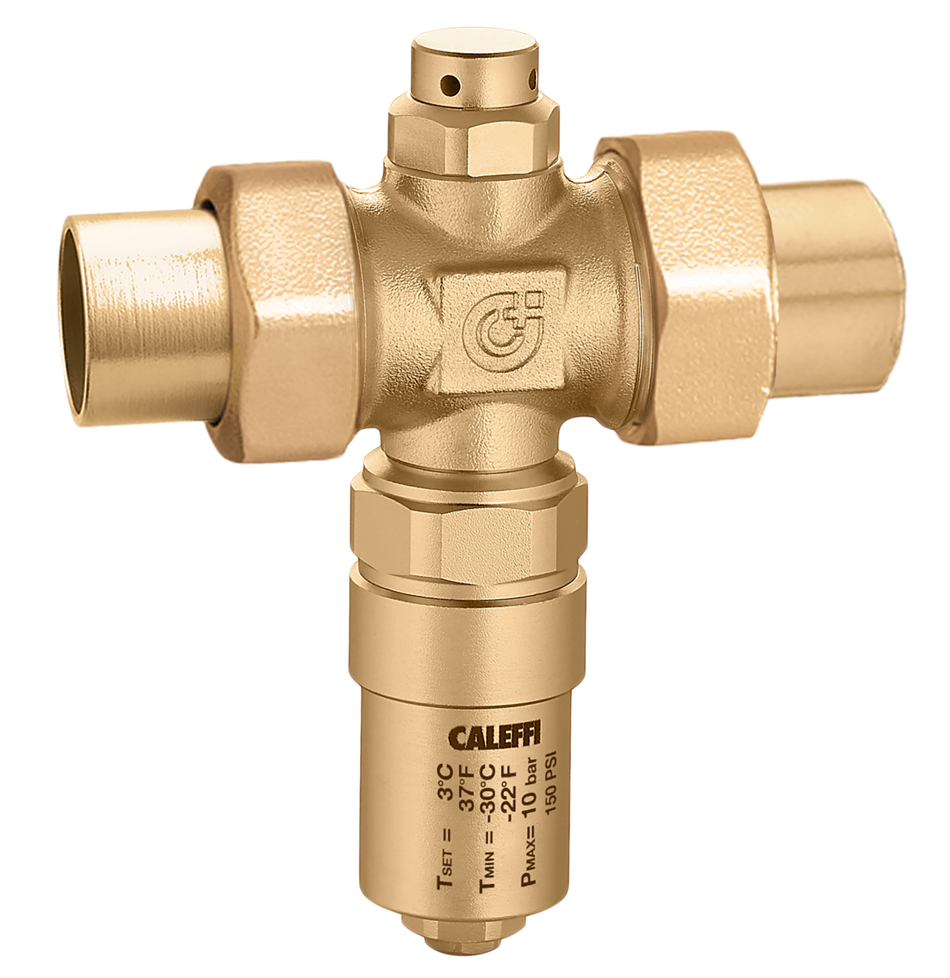
Anti-freeze valve for air-to-water hydronic heat pump applications
Technical data
Drawings and specifications
| Part number | Connection | Actions | |
|---|---|---|---|
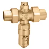
| 108860A | 1 1/4" NPT female union |
||
|
3D models
Tender text
CALEFFI, 108860A, iStop®.
Anti-freeze valve for air-to-water hydronic heat pump applications
connection: 1 1/4" NPT female, union. Maximum operating pressure: 150 psi. Ambient temperature range: -22 – 140 °F. Material: brass.
|
|||
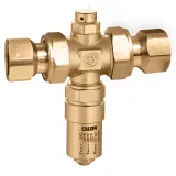
| 108866A | 1" Press union |
||
|
3D models
Tender text
CALEFFI, 108866A, iStop®.
Anti-freeze valve for air-to-water hydronic heat pump applications
connection: 1" Press, union. Maximum operating pressure: 150 psi. Ambient temperature range: -22 – 140 °F. Material: brass.
|
|||
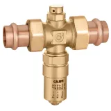
| 108869A | 1" sweat union |
||
|
3D models
Tender text
CALEFFI, 108869A, iStop®.
Anti-freeze valve for air-to-water hydronic heat pump applications
connection: 1" sweat, union. Maximum operating pressure: 150 psi. Ambient temperature range: -22 – 140 °F. Material: brass.
|
|||
| 108870A | (not used) 1 1/4" F union |
||
|
3D models
Tender text
CALEFFI, 108870A, iStop®.
Anti-freeze valve for air-to-water hydronic heat pump applications
connection: (not used) 1 1/4" F, union. Maximum operating pressure: 150 psi. Ambient temperature range: -22 – 140 °F. Material: brass.
|
|||
| 108876A | 1 1/4" Press union |
||
|
3D models
Tender text
CALEFFI, 108876A, iStop®.
Anti-freeze valve for air-to-water hydronic heat pump applications
connection: 1 1/4" Press, union. Maximum operating pressure: 150 psi. Ambient temperature range: -22 – 140 °F. Material: brass.
|
|||
| 108879A | 1 1/4" sweat union |
||
|
3D models
Tender text
CALEFFI, 108879A, iStop®.
Anti-freeze valve for air-to-water hydronic heat pump applications
connection: 1 1/4" sweat, union. Maximum operating pressure: 150 psi. Ambient temperature range: -22 – 140 °F. Material: brass.
|
|||
Find your nearest Caleffi Representative
Faq - Frequent questions
In reality, there is no clear answer to this question. The answer is "it depends". The automatic fill valve is not necessary for the frost protection valve to function correctly, i.e. in an installation where there is no automatic fill valve, the 108 series valve will function correctly. However, there are situations in which the automatic filling valve, in combination with the frost protection valve, is necessary to fully protect the heat pump. This is the case, for example, with a non-standard heat exchanger connection, as in the figure below, where (9) is the plate heat exchanger, (10) the system supply and (11) the system return.
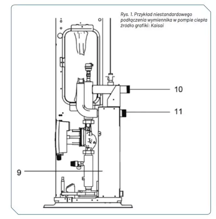
Example of the connection of a non-standard heat exchanger in a heat pump
graphic source: Kaisai
In the situation shown, the automatic filling unit is required to circulate water through the entire heat exchanger and the part of the system below the return pipe. Without it, the water might stand still somewhere, for example in the lower part of the exchanger.
This is precisely an example of an installation where an automatic filling valve is required. In reality, however, installed in any installation, even one that apparently does not require it, it offers some advantages. It eliminates the need to bleed the system after the anti-freeze valve has been activated. It protects the pump from going into emergency mode in the event of a major loss of water if the power failure lasts for a prolonged period.
Another extremely important issue that raises the subject of pressure losses in the system. The antifreeze valve is a full flow valve and generates very low pressure losses, negligible in hydraulic calculations. The valve is designed in such a way that there are no parts that can offer significant resistance.
The use of a reduction, for example when fitting a 1" valve to a 5/4" pipe, will obviously generate a greater pressure loss, but this loss will still be relatively small. Therefore, we should not fear this type of mounting, especially since we normally mount other elements on the system, such as strainers, which are much more resistant.
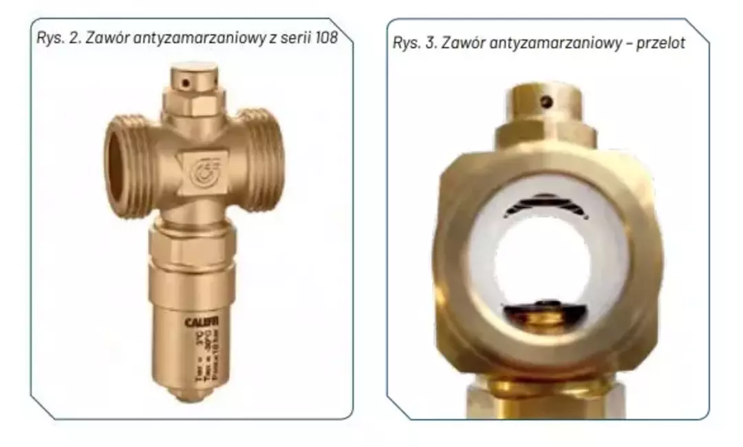
Do not isolate valve 108. In the event of a power failure, the valve must be the point where the water cools fastest. If we insulated the part of the valve where the thermostatic sensor is located, there would be a risk that the water would cool faster in another part of the system. For example, if the insulation of the heat exchanger of the heat pump was less than that of the frost valve. In this case, the water in the heat exchanger could cool earlier. If the vacuum breaker (the element at the top of the valve whose job it is to introduce air into the system when water drips from the valve) is insulated, the valve might not work at all because its purging would be blocked. This situation could occur in an installation where there is no automatic fill valve.
La valvola in questione non è una valvola di scarico e la sua funzione non è quella di scaricare l'acqua dal sistema. Quando la temperatura dell'acqua nella sezione esterna del circuito raggiunge i 3 °C, la valvola apre lo scarico dell'acqua, che si manifesta con un leggero gocciolamento. Non appena l'acqua dell'edificio entra nella valvola a una temperatura superiore a 4 °C, il sensore termostatico della valvola chiude lo scarico dell'acqua. Ciò comporta una situazione in cui la valvola funziona "a intermittenza" anziché gocciolare in continuazione. A causa della piccola differenza tra la temperatura di apertura e quella di chiusura, la quantità di acqua scaricata è ridotta. Il compito della valvola è quello di mantenere il flusso d'acqua continuo per la sezione esterna del sistema, ad esempio attraverso lo scambiatore della pompa di calore, mantenendo così l'acqua a una temperatura superiore a 3 °C.
For proper functioning, the frost valve must be installed in 2 pieces. One valve must be installed in the flow and one in the return, as close to the heat pump as possible. For complete protection of the heat source, 2 valves are required because you can never be sure where in the system the water cools down the fastest, and it may not always be the return of the system. There are several factors that can influence where the water cools in the system, including, for example, weather conditions.
MISSING