Code 4.005
Medium-large hybrid system: heating and domestic hot water with dual storage
PDF
DXF


The system comprises:
- Two heat pumps, one dedicated exclusively to heating and one for both heating and domestic hot water production
- A manifold to which the machines are connected
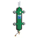
- A hydraulic separator which also functions as a buffer tank for storing the energy required for the machines to work properly
- Two storage tanks for domestic hot water production
- A module with boilers in cascade so that the supplied power can be modulated
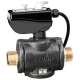
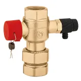
- Safety devices specified by INAIL regulations, as the power level is over 35 kW
- A hydraulic separator, after the boiler module, dividing the primary circuit from the secondary circuit
- Two booster circulators; in this configuration the heating function and domestic hot water production can be maintained at the same time for the HPs and for the boiler unit
Hot water production takes place via a circuit fitted with:
- A first storage tank for pre-heating connected to one of the two heat pumps by means of a three-way priority valve
- A second storage tank inside which is a coil connected to the chill water circuit, with the task of completing the pre-heated domestic water heating phase in the first storage tank
This solution applies to medium-large systems, in which the heating function and domestic hot water production can be maintained at the same time for the heat pumps and for the boiler unit.
In fact, the layout allows operation in various configurations:
- Both generators for heating. All generators contribute to the production of hot water for heating, using the methods suggested in the figure. Where necessary, in partial load conditions, the heating may only be generated by a heat pump or by both, keeping the boiler as an auxiliary generator.
Both generators for domestic hot water. The DHW is pre-heated by the heat pump in the first cylinder; the boiler increases the temperature to higher levels in the second.
Caleffi S.p.a. declines any responsibility arising from improper use of the data contained in this document. The diagrams are not a substitute for HVAC system design.
