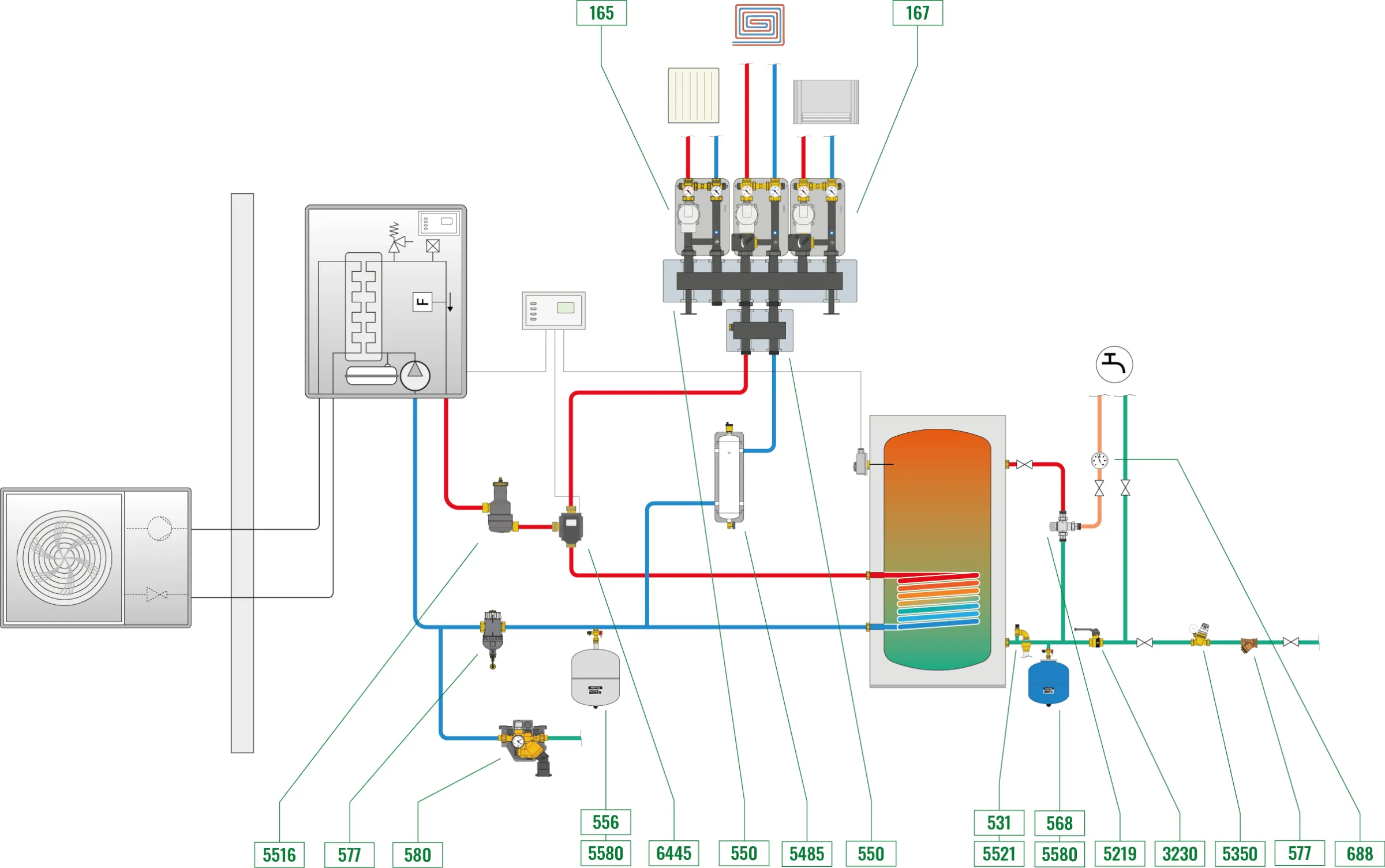

The system consists of a primary circuit which includes:
- Split heat pump
- Water treatment devices (dirt separator and deaerator) for the protection of generators and, more generally, all system components
- Diverter valve for priority domestic hot water production
- Inertial storage to guarantee a minimum operating volume for the machine
- System charging unit with pressure reducing valve and backflow preventer
The secondary circuit consists of:
- Distribution manifold with hydraulic separator
- Direct supply unit serving the radiator circuit
- Distribution and thermostatic regulating unit serving the fan-coil and radiant panel circuit
The solution is suitable for systems in which the heat pump circulator is not capable of directly supplying the heating and cooling system, or where there are specific features which necessitate the creation of a primary side and a secondary side. The following operating modes are possible:
- Priority domestic hot water (DHW) production
- Independent heating and cooling with different capacities and defrost cycle
Connection to the low-volume hydraulic separator speeds up heating and cooling system installation and allows the heat pump to carry out a defrost cycle even when no request for heating or cooling has been made. This configuration also allows booster units to serve their dedicated systems without interference between them.
Note: The control, expansion and safety equipment must be sized according to the heating capacity and specific characteristics of the system, in compliance with current legislation. The electrical connections must be assessed in liaison with the relevant organisations to guarantee observance of operational and regulatory requirements. This configuration can also work with the self-contained version, if the external pipe and antifreeze valves are added.


