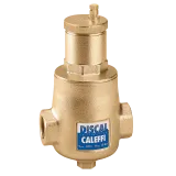
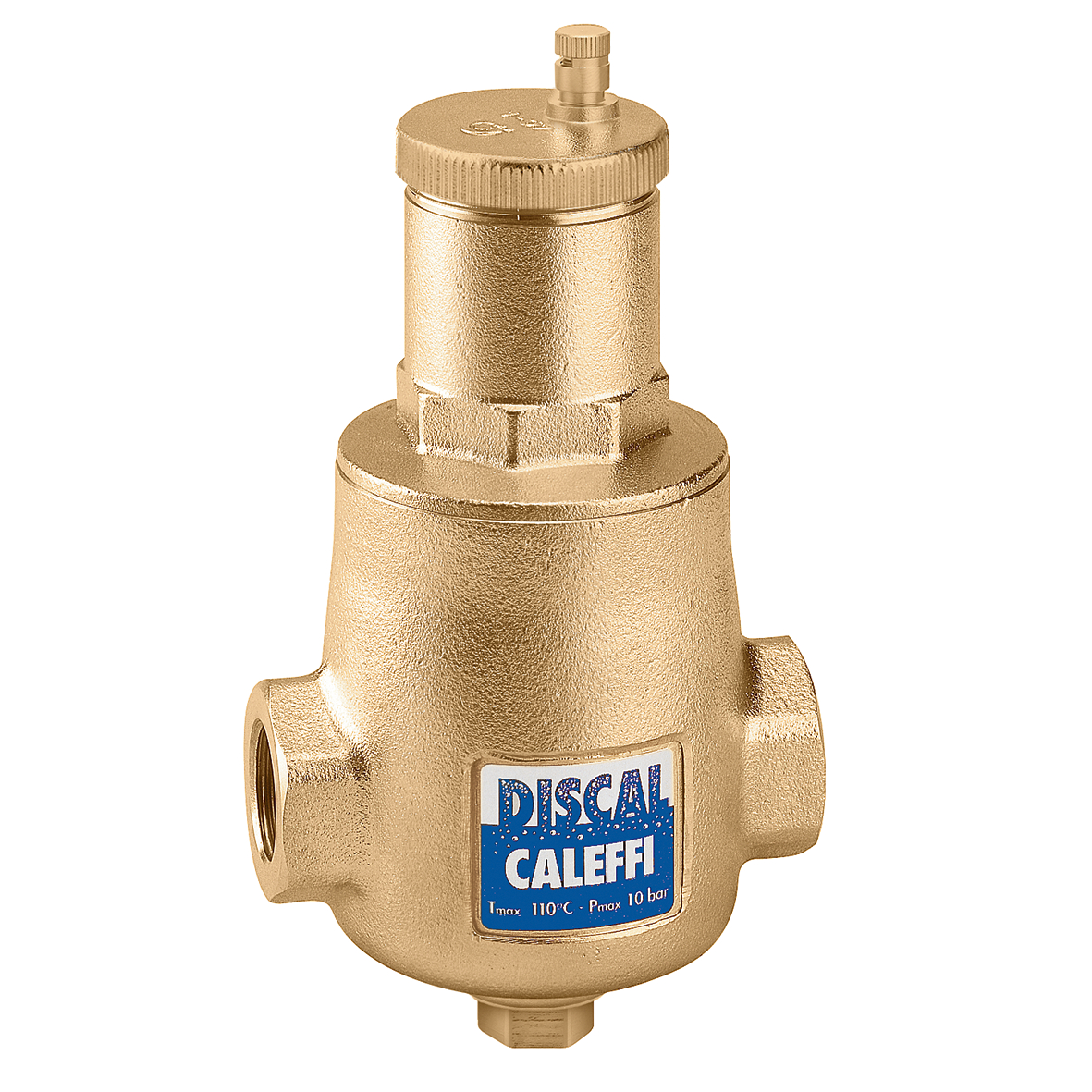
DISCAL®, Brass deaerator.


Product Description
Brass deaerator.
Technical data
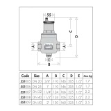
Drawings and specifications
| Part number | Connection | Actions | |
|---|---|---|---|
| 551005 | G 3/4" (ISO 228-1) F |
||
|
2D drawings
dwg
Share this file
Download this file
dxf
Share this file
Download this file
dxf
Share this file
Download this file
3D models
Tender text
CALEFFI, 551005, DISCAL®.
Brass deaerator.
Connection: G 3/4" (ISO 228-1) F. Maximum working pressure: 10 bar. Maximum air discharge pressure: 10 bar. Medium temperature range: 0–110 °C. Material: brass.
SCIP code
d8d60454-6e27-422d-9b30-8812a4e6f934
|
|||
| 551006 | G 1" (ISO 228-1) F |
||
|
2D drawings
dxf
Share this file
Download this file
dxf
Share this file
Download this file
dwg
Share this file
Download this file
3D models
Tender text
CALEFFI, 551006, DISCAL®.
Brass deaerator.
Connection: G 1" (ISO 228-1) F. Maximum working pressure: 10 bar. Maximum air discharge pressure: 10 bar. Medium temperature range: 0–110 °C. Material: brass.
SCIP code
d8d60454-6e27-422d-9b30-8812a4e6f934
|
|||
| 551007 | G 1 1/4" (ISO 228-1) F |
||
|
2D drawings
dwg
Share this file
Download this file
dxf
Share this file
Download this file
3D models
Tender text
CALEFFI, 551007, DISCAL®.
Brass deaerator.
Connection: G 1 1/4" (ISO 228-1) F. Maximum working pressure: 10 bar. Maximum air discharge pressure: 10 bar. Medium temperature range: 0–110 °C. Material: brass.
SCIP code
d8d60454-6e27-422d-9b30-8812a4e6f934
|
|||
| 551008 | G 1 1/2" (ISO 228-1) F |
||
|
2D drawings
dwg
Share this file
Download this file
dxf
Share this file
Download this file
3D models
Tender text
CALEFFI, 551008, DISCAL®.
Brass deaerator.
Connection: G 1 1/2" (ISO 228-1) F. Maximum working pressure: 10 bar. Maximum air discharge pressure: 10 bar. Medium temperature range: 0–110 °C. Material: brass.
SCIP code
d8d60454-6e27-422d-9b30-8812a4e6f934
|
|||
| 551009 | G 2" (ISO 228-1) F |
||
|
2D drawings
dwg
Share this file
Download this file
dxf
Share this file
Download this file
3D models
Tender text
CALEFFI, 551009, DISCAL®.
Brass deaerator.
Connection: G 2" (ISO 228-1) F. Maximum working pressure: 10 bar. Maximum air discharge pressure: 10 bar. Medium temperature range: 0–110 °C. Material: brass.
SCIP code
d8d60454-6e27-422d-9b30-8812a4e6f934
|
|||
This application allows for sizing and making calculations for pipes and conduits carrying water or air, respectively for hydraulic or aeraulic plants.
Faq - Frequent questions
These are devices that, thanks to their special structure, are able to separate microbubbles from the flowing medium. The active part of the valve consists of an element that causes flow turbulence, which facilitates the release of microbubbles. Air bubbles combine with each other, increasing their volume. They then rise to the top of the device, where they are collected and later released by an automatic vent valve. Air separators are mounted on the installation's power supply line just behind the heat source, which is extremely important because this is where the greatest accumulation of microbubbles occurs.

