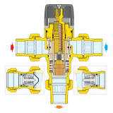
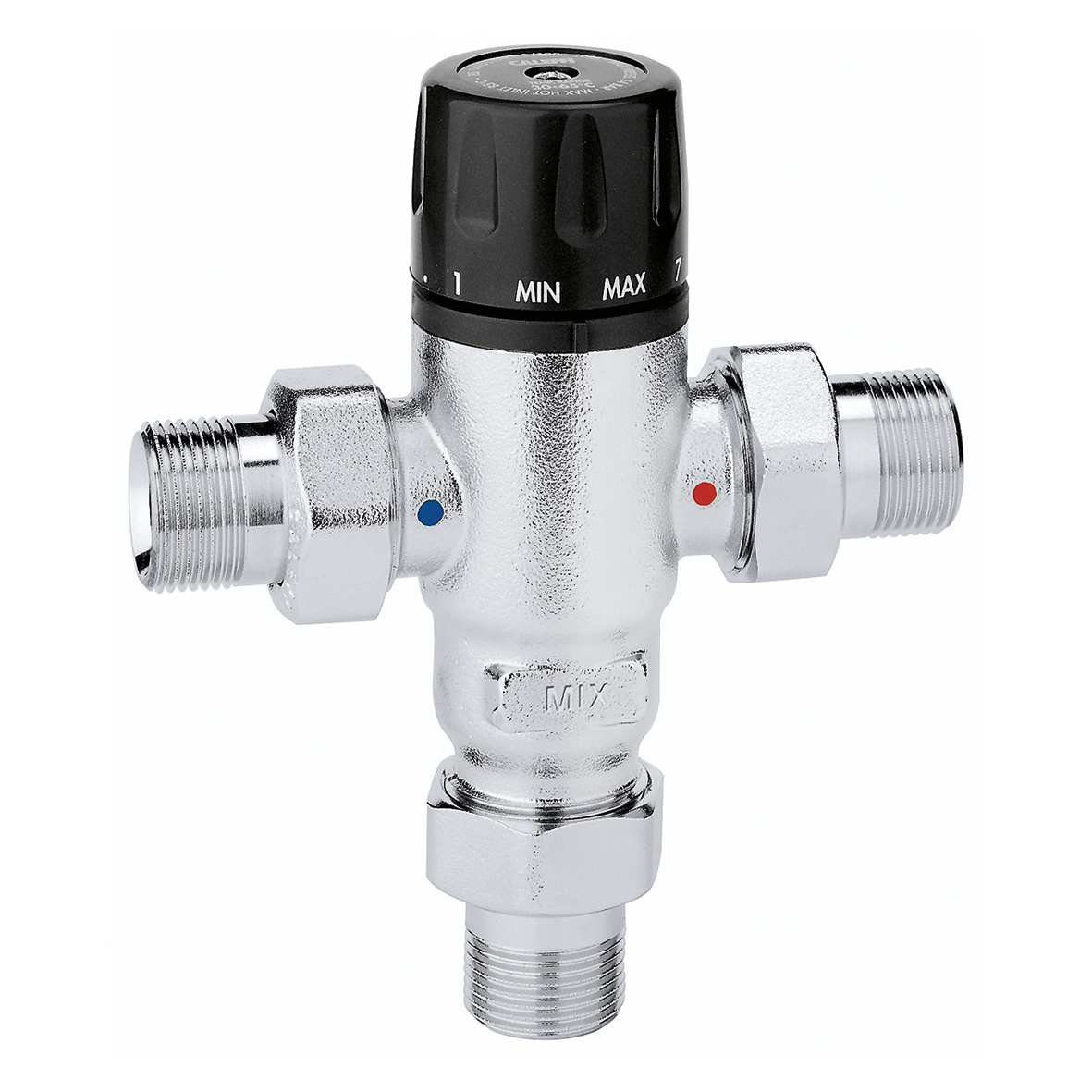
Adjustable anti-scale thermostatic mixing valve.


Product Description
Adjustable anti-scale thermostatic mixing valve.
PATENT
Technical data
Certifications


Drawings and specifications
| Part number | Connection | Note | Adjustment temperature range | Actions |
|---|---|---|---|---|
| 521400 | G 1/2" A (ISO 228-1) M union |
- | 30–65 °C | |
|
Kv
2,6 m³/h
|
||||
|
2D drawings
dwg
Share this file
Download this file
dxf
Share this file
Download this file
3D models
stp
Share this file
Download this file
igs
Share this file
Download this file
Tender text
CALEFFI, 521400.
Adjustable anti-scale thermostatic mixing valve. Connection: G 1/2" A (ISO 228-1) M, union. Maximum working pressure: 14 bar. Medium temperature range: 2–85 °C. Adjustment temperature range: 30–65 °C. Finish: nickel plated. Kv: 2,6 m³/h. Material: dezincification resistant brass DR "low lead".
SCIP code
8f1fcbd4-9853-42cd-ab3f-2d3eab10bd6b
|
||||
| 521500 | G 3/4" A (ISO 228-1) M union |
- | 30–65 °C | |
|
Kv
2,6 m³/h
|
||||
|
2D drawings
dwg
Share this file
Download this file
dxf
Share this file
Download this file
3D models
igs
Share this file
Download this file
stp
Share this file
Download this file
Tender text
CALEFFI, 521500.
Adjustable anti-scale thermostatic mixing valve. Connection: G 3/4" A (ISO 228-1) M, union. Maximum working pressure: 14 bar. Medium temperature range: 2–85 °C. Adjustment temperature range: 30–65 °C. Finish: nickel plated. Kv: 2,6 m³/h. Material: dezincification resistant brass DR "low lead".
SCIP code
70e939a8-76da-45ff-a852-9f0acf55c3d0
|
||||
| 521503 | G 3/4" A (ISO 228-1) M union |
With check valves | 30–65 °C | |
|
Kv
2,6 m³/h
|
||||
|
2D drawings
dwg
Share this file
Download this file
dxf
Share this file
Download this file
3D models
stp
Share this file
Download this file
igs
Share this file
Download this file
Tender text
CALEFFI, 521503.
Adjustable anti-scale thermostatic mixing valve. Connection: G 3/4" A (ISO 228-1) M, union. Maximum working pressure: 14 bar. Medium temperature range: 2–85 °C. Adjustment temperature range: 30–65 °C. Finish: nickel plated. Kv: 2,6 m³/h. Material: dezincification resistant brass DR "low lead".
SCIP code
1e8aa1e7-c413-45d3-bc94-d4b9efdb5963
|
||||
Faq - Frequent questions
The basic task is to protect the user against burns. In hot water installations, the water temperature at the point of consumption, in accordance with applicable regulations, should be 55 - 60 °C. Such requirements are related to preventing the growth of Legionella bacteria in the installation. Using water at such temperatures may be hazardous to health. Below I have included a chart showing how long a burn can occur. The use of this type of valves is also intended to ensure user comfort and save energy by reducing heat losses in the installation.
A common mistake when selecting thermostatic mixing valves is to select them solely based on the connection diameter. This method may result in the use of a device with too low capacity or an oversized valve. This may result in:
if the valve is too small: lack of adequate required flow rate; too high a flow rate, which may result in noisy valve operation or faster wear.
if the valve is too large: deterioration of the speed and accuracy of temperature control
The correct selection should be made based on the required flow, calculated in relation to the number and type of draw-off points, taking into account simultaneous operation factors.
The temperature of the mixed water is most often set using a valve knob with a numerical scale, the individual numbers correspond to the temperature of the mixed water. Here it should be noted that the mixed water temperature values are correct for the reference conditions. In the case of different values of water temperature, cold and hot, when making the setting, measure the temperature of the water mixed at the point of consumption and adjust it using the knob to the required value.
Giving the valve setting on the knob in temperature form may be misleading and result in incorrect valve setting.
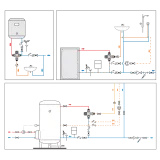
To ensure proper operation of this type of valves, it is recommended to use non-return valves installed in the cold and hot water pipes. Such elements protect the valve against the possible negative impact of the high pressure difference occurring between the hot and cold water installations, and also prevent the natural circulation of the medium during periods of no water consumption.
Additionally, it is worth protecting the valve against contaminants in the water by using filters.